Related articles:
– The “Zero-stock” catalogue and its power
– What parts should be in your Maintenance Stores?
– Equipment criticality ratings
I could easily argue that spare parts lists are the most valuable source of information for Maintenance people, because they make it easy to find the right parts for all your equipment, every time, without having to search through the Stores material catalogue.
Spare parts lists are sometimes called “Bills of Materials” (or “BoM’s”) but for this article I will call them “Parts lists” because the term “Bill of Materials” implies that the list contains all parts for a piece of equipment, and may be confused with a list of materials for work orders.
Parts lists have the primary purpose of linking the two key databases, the Equipment Register and the Materials Catalogue, by showing which catalogue items are used on each item of equipment. A simple parts list is shown below:
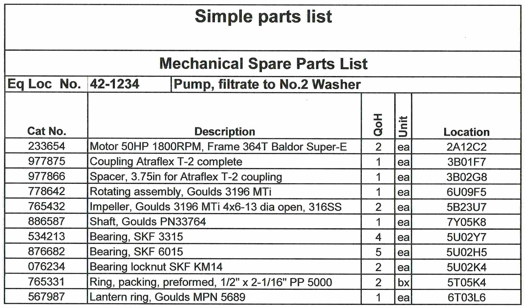
The above list is typical of some older maintenance computer systems with very limited functionality, and while of considerable value, it lacks a great deal of information that is needed for good maintenance. It is also limited to one level in the equipment/materials hierarchy, so the list contains parts of parts (e.g. the bearings for the rotating assembly) which makes parts list maintenance more difficult.
A comprehensive parts list should include much more information in a very logical structure, including:
– parts lists for assemblies listed in the materials catalogue as well as parts lists for equipment locations.
– parts and assemblies which are not stocked.
– free-issue items, such as fasteners and small pipe fittings.
– special tools.
– explanations of where and how materials catalogue items are used in assemblies.
– manufacturer’s manuals.
– links to important information, such as drawings, manuals and engineering data.
– other useful maintenance information, such as alternative parts.
Examples of well-structured and comprehensive parts lists for an equipment location (a pump) that contain all of the above features are shown below. These examples have four “levels” and each numbered item is explained. Note that these lists are called “Parts, tools and information” lists because they do much more than just linking catalogued parts to equipment numbers.
The ability of maintenance computer systems to support this level of detail varies widely, and system options are reviewed at the end of this article.
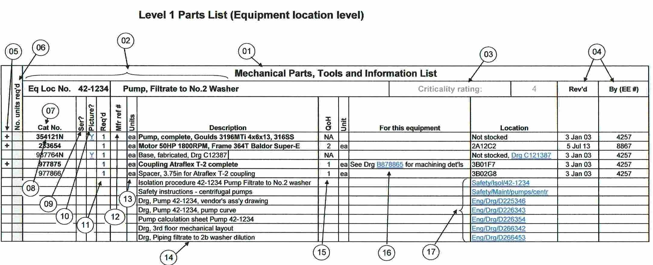
“Level 1” parts list
This list is for the major components which together perform a processing function, in this case, pumping Filtrate to “No.2 washer” in a chemical processing plant.
“Level 1” is the first level below an “Equipment Location”, as described in the article “Asset identification and numbering“.
Refer to the circled numbers in the illustrations for the following explanations.
01 – It is common to separate mechanical and electrical parts lists, however if they are combined, there should be a filter to enable just electrical or just mechanical parts to be viewed.
If separate mechanical and electrical parts lists are created they should use exactly the same format and logic. It is not uncommon for the mechanical and electrical departments to march to their own drummers, so the person responsible for the parts management business process needs to ensure that a uniform approach is used.
02 – At Level 1, the parts listed are for the Equipment Location, for which the Equipment Number and the equipment description must be shown in the header.
03 – Parts and assemblies may be assigned criticalities which could have some value, especially for the management of repairable spares. Your maintenance computer may support the management of critical spares, e.g., with brightly coloured bin labels, frequent physical counting, reporting of overdue repairable items, etc.
04 – Good management of spare parts information should include recording changes made to parts lists.
05 – Many systems use the “Windows” convention of a “+” sign to indicate that a row can be expanded to show more detail. In this example, clicking on a “+” will open the next lower level of parts for materials catalogue items, as shown below. In the example, items with a lower level of parts are in a bold font.
06 – If supported by your maintenance computer system, a field to generate a “pick list” is of value. For repairs to this pump, entering the number of units required would add items to the materials issue request for the work order covering the repair.
07 – The term “Catalogue number” is used as both stocked and non-stock parts are included.
08 – The items listed at each level must include items that are not stocked, and for which other parts are stocked or catalogued.
Here the complete pump is not stocked, but because it is an assembly which includes some stocked and catalogued parts, it must be assigned its own materials catalogue number and be included in the “Level 1” parts list. In this example, parts which are catalogued but not stocked are identified by an “N” suffix. This suffix is not mandatory, but it is useful to immediately differentiate between stocked and non-stocked parts (see “Zero-stock catalogue and its power” for more details including special system functionality requirements).
09 – “Ser?” – This column is used to identify parts which are serialized, i.e. repairable spares where each individual unit is assigned a serial number and its history and location is tracked and recorded.
10 – “Picture?” – This column is to identify items which have a picture or drawing. The “Y” should be a link, i.e. clicking on the “Y” will open the picture or drawing.
11 – “Req’d” shows the number of units used in the assembly.
12 “Mfr’s ref #” is the number of the part shown on the parts drawing in the manufacturer’s catalogue. See the “Level 2” illustration for examples.
13– “Units” is the unit of issue for each item.
14 – “Description”. This description is copied from the Materials Catalogue and may be truncated so that all columns will fit on the parts list. If a good standard of data entry (see “Naming parts“) is used for parts descriptions, this is unlikely to cause any problems.
15 – “QoH” – quantity on hand for stocked items. Non-stocked items show “NA”.
16 – “For this equipment”.
This is an extremely valuable and important field and is available in all good maintenance computer systems, although various names such as “Cross-reference” may be used for the field name. Frequently, the use of this column is not understood and it is used for other information, such as part drawings and other information that applies to the part wherever it is used and should be in an appropriate field in the materials catalogue.
Information entered in this field appears only on the parts list and not in the materials catalogue. In this example, this column contains a link to a drawing that shows how the coupling is to be bored and keyed for this pump and its motor.
This column is explained in more detail under “Level 2” parts lists.
17 – To provide maintenance people with “one-stop shopping” for all parts information, parts lists should include links to important documents that are required for equipment operation and maintenance, including safety and isolation procedures. Links may be to files on the local server, or to manufacturers’ or vendors’ web sites as appropriate.
These items do not require catalogue numbers, although special tools (see “Level 2” below) should be included in the materials catalogue (perhaps with a “T” suffix for their catalogue numbers). Hard copies of manufacturer’s operating and maintenance manuals in the technical library lend themselves to being managed by the same business process that is used for managing tools and may also be given materials catalogue numbers.
“Level 2” parts list
18 – This list is the highest level for the parts for an item which is listed in the Materials Catalogue.
This example is for a process pump, which is not stocked as a complete pump. Note that the header information is still for a mechanical parts list, but it is now for a materials catalogue assembly, and not an equipment location.
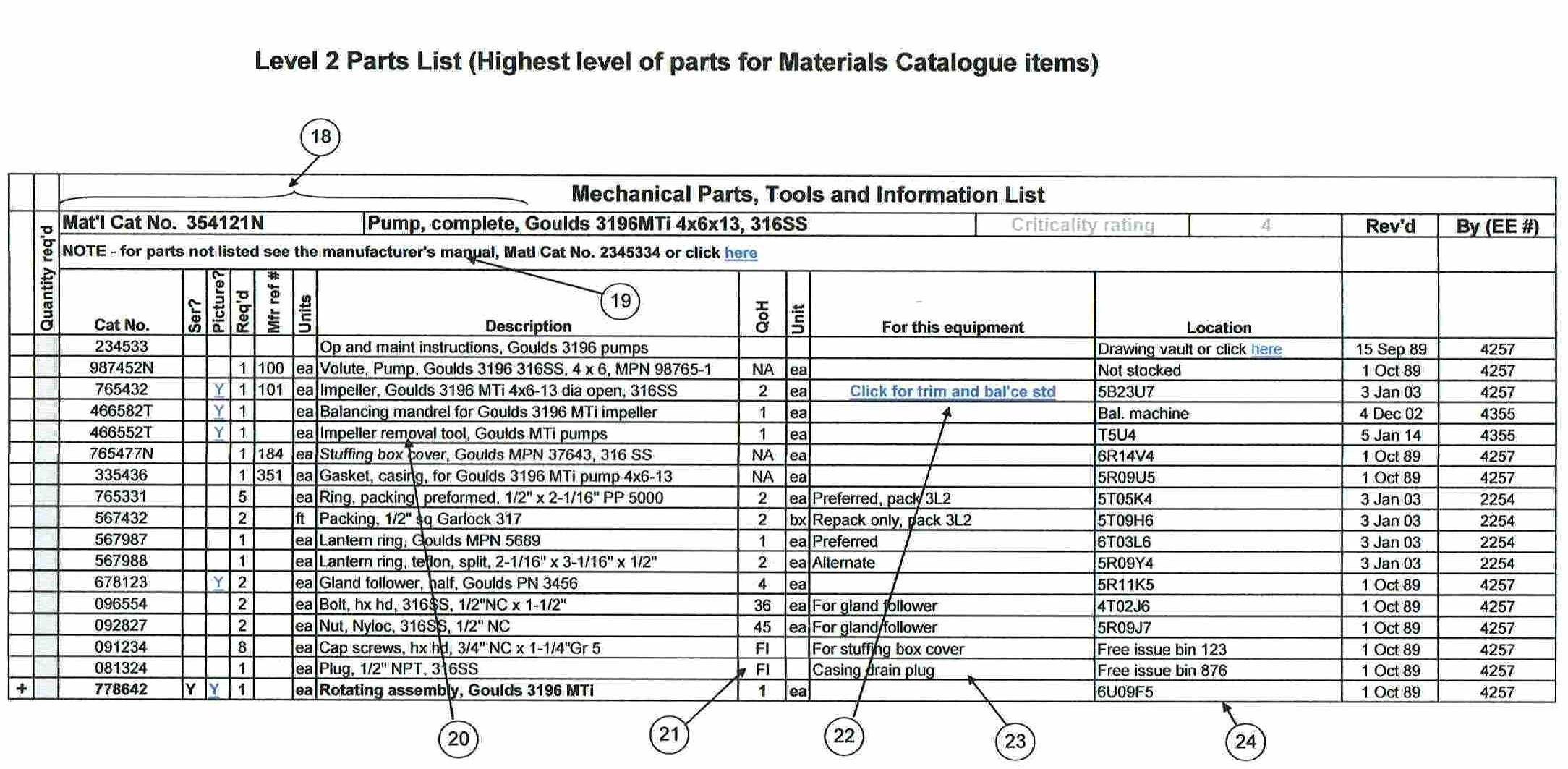
19 – Not all parts in an assembly need to be listed. All stocked items must be included, as well as non-stocked parts that are important maintenance items, or for which application information is required in the “For this equipment” column.
For items which are not shown, a link to the manufacturer’s manual containing parts information should be included. In this case there is also a hard copy of the manual which has been assigned a materials catalogue number.
20 – Special tools should always be included in parts lists. For some maintenance work, even to replace a single component, several tools are required. Using the right tools is every bit as important as using the right parts for any maintenance work and our observation is that improving the management of tools is often an area of opportunity.
21 – Small parts are just as important as large components for work execution. Where “Free issue” items are required, they should be included in the parts list.
22 – This is critical engineering data. Some information, such as impeller trim diameters, are very critical to reliable equipment operation and the entry and editing of this information must be strictly controlled. In this example, the link is to a read-only Engineering file showing the impeller trim diameters for all equipment locations where the pump shown in this Level 2 parts list header is used.
At level 2, the “For this equipment” information describes how each material catalogue item is used in the pump assembly and NOT in the equipment location shown in the header in the Level 1 parts list, so the impeller trim diameter can not be entered directly in the “For this equipment” column.
An alternative here would be to show the impeller as a line item in the Level 1 parts list, with the trim diameter in its “For this equipment” column, but this would be a departure from the logical structure and should be avoided. Also, unless the maintenance computer has the ability to provide different levels of security to protect the data in individual cells, this critical information would then be much less secure.
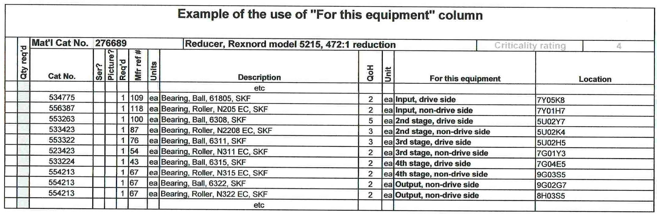
23 – This shows some other typical information that can be included in the “For this equipment” column, such as preferred options where more than one exist, where various parts are used in the assembly, packing sequences, etc.
Where there are many parts with similar descriptions, using the “For this equipment” column to show the location of the parts in the assembly is very helpful, as in the illustration below which is extracted from the parts list for a four-stage reduction gearbox.
This column could also be used for interchangeable parts. For example, in the Level 1 parts list there may be an option to use an alternative motor with a different frame size, and the entry could be something like “Alternative motor Cat. No. 233729. Requires adaptor base Cat. No. 239745 and should be returned to stock as soon as possible because it is the only spare for No. 3 feed water pump, 11-2276”. To minimize the space required on parts lists, this kind of detailed information should be accessed through a link in the “For this equipment” column, e.g. “Click for alternative motor“.
24 – The parts list should show the location of all items listed, which may include web site links for documents. Most of the locations listed (e.g. 5B23U7) are Stores bin numbers.
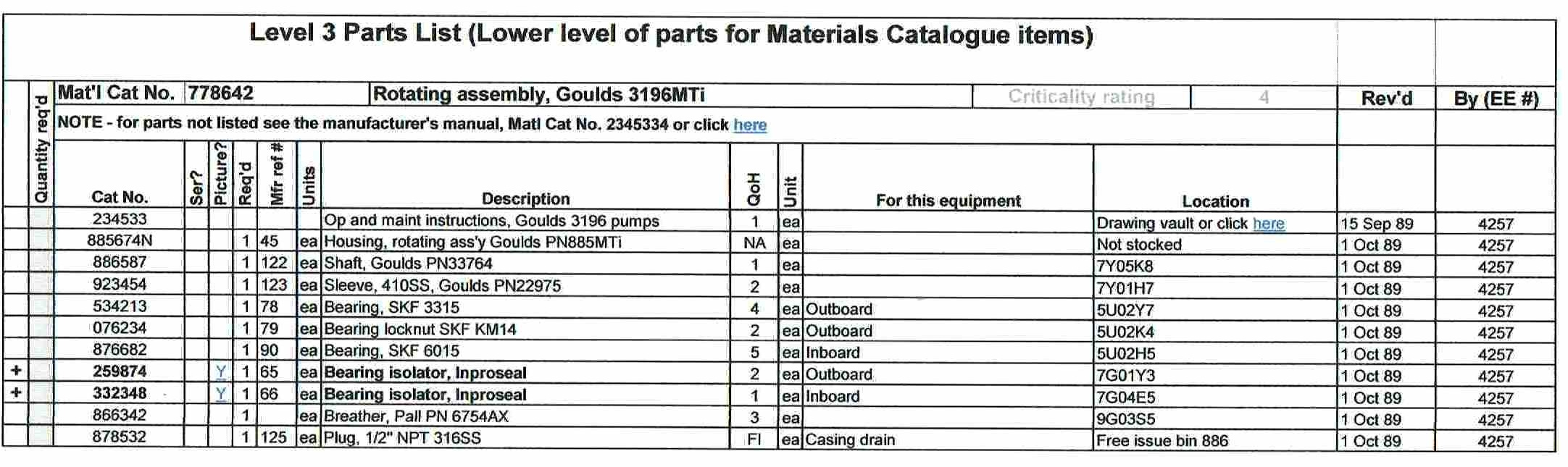
“Level 3” parts list
This list is the next level in the hierarchy, and contains the list of parts, tools and information for an assembly that is included in the Level 2 list.
The “Level 4” parts list (o-rings, etc, for the bearing isolators) is not shown.
Note that there may be multiple Level 2, Level 3, etc parts lists for any equipment location.
Responsibility for parts lists
Parts lists should be created as part of any project to install new equipment, and should be clearly defined as the responsibility of the project manager – although experience has shown me that getting engineers to take an interest in spare parts list is similar to pulling teeth, and often needs follow up.
The maintenance of spare parts lists should be a Maintenance responsibility, and is one non-planning function that is appropriate to add to a Planner’s job description. Planners should review all work orders when they are closed and in the process check for tradespeople’s notes, which may include a request to add parts used on equipment to the parts lists.
Where tradespeople are “shop specialists” and rebuild equipment they should be given the authority to add parts to parts lists. They are often the only people to see such information as bearing or seal manufacturers’ part numbers when equipment is disassembled. Adding these to the parts lists allows them to be purchased from the component manufacture at a fraction of the price that the equipment manufacturer would charge.
Parts lists creation and maintenance MUST NEVER be a Purchasing or Stores responsibility. Parts list content must be based on technical knowledge of the equipment and its operating context.
A good practice is to assign overall responsibility for parts lists to a senior manager, with department responsibilities assigned to area Maintenance Engineers.
“Automatic” parts lists generation
Some maintenance computer systems have the functionality to automatically create parts lists by matching the materials catalogue numbers of parts drawn from Stores against a work order to the equipment number to which the work order is charged.
This is a dangerous practice unless there is unusually strict control over the work order system. Parts can easily end up on the wrong parts list – I have seen a parts list for a small fan with a single belt drive with 5 different belts on its parts list. Also, parts will be added to the “Level 1” parts list, where they may not belong.
If an automatic parts list generation system is used, it should be configured to do no more than create a report at frequent intervals (e.g. weekly) showing all new parts which have been charged to equipment and which are not already on their parts list. This report should be reviewed by an area equipment expert, such as the Maintenance Engineer, who should verify the accuracy of the information and then add valid items to the correct parts list.
System requirements
Few maintenance computer systems have the functionality to build spare parts lists as described in this article. Some come close, and some may even be better, but many have very limited capabilities.
There is one fact of life that has a major impact on spare parts lists, and that is that many maintenance computer systems have a short life. In this age of companies being taken over by new owners through sales and mergers, systems may be changed without the impact on equipment information being fully considered, especially if the new system is a company-wide financial system with a “maintenance module”. Maintenance systems from different vendors have widely varying degrees of compatibility and data is frequently compromised when systems are replaced.
Many person-years of effort can go into building good parts lists, and all this effort can be lost if a new system is carelessly implemented. Recent examples I am aware of include a new system being unable to list non-stocked spares and rolling all levels of parts list up to a single “Level 1”, in the process undoing much conscientious work and losing valuable maintenance data. I have also seen a system implemented which had no capability for managing parts lists at all.
I personally like the use of standard software, such as MS Excel, to store parts lists, with secure templates and controlled “write” access. These files should be located on a server which is frequently backed up and which provides ready “read only” access to all users. Access to these files from the maintenance computer system equipment register using links will protect the parts lists from all system changes. Standard software also provides excellent flexibility when designing the format and content of parts lists, although it has some downsides – for example, its unlikely that Excel can support the generation of “pick lists” as described under item “06” above, and it may be a problem creating an interface that would keep “quantity on hand” and “bin numbers” up to date.
Design the parts lists before entering data
For most of my readers, this advice is probably too late. As can be seen from this article, the content and format of parts lists requires thoughtful and experienced design input and once the data has been entered it may take considerable effort to, for example, add and populate another column.
The additional information included in the comprehensive parts lists described in this article (compared to the simple parts list) takes little time to enter when new parts lists are created, and for existing equipment this information can be entered as time permits or as repair work is planned.
Parts lists require dedicated effort
As mentioned, generation of complete parts lists for a large operation may take years, and their maintenance requires continuing disciplined effort. However, if you are faced with a project to create a new set of parts lists from scratch, the return can be very fast if you start with those items of equipment which require the most frequent corrective maintenance where parts are used. You may be able to identify this equipment from your work order history, and if not, you will get close by interviewing experienced area maintenance and operating supervisors, tradespeople and operators (see “Pareto Power in Maintenance“)
Click here to return to the articles list
Management is getting people to do what you want them to do.
Leadership is getting people to want to do what you want them to do (dsa).
© Veleda Services
Don Armstrong, P. Eng (retired)
President, Veleda Services
dsarmstrong@shaw.ca
250-655-8267 Pacific Time